Ship Construction: Plate Machining, Assembly of Hull Units And Block Erection
In the last article we discussed how material is shifted from the stockyard to the surface treatment plant, then marked, nested and cut to required shapes. We also discussed the methods used to carry out the above processes.
This article will take the material flow forward. We will see how the plates and sections are given shape and curvature according to the design of the hull. Following surface preparation, machining of plates and sections are carried out in the hull shop where they are made ready to be welded into two dimensional and three dimensional structures.
Plate Bending
A ship’s hull usually has multiple curvatures (unless only straight plates are used in the design). It might seem quite easily achievable on a 3D modelling software package, but production of the same is not. To bend and develop steel plates and stiffeners to required 3D curvatures in order to make them fit the shape of the hull, special methods are used by a shipyard.
Before understanding these processes, it is important to appreciate two very important aspects of developing curved surfaces. There are two basic types of 3D geometries:
- Non Developable Surface: These are 3D surfaces which cannot be achieved by direct rolling or hydraulic bending of straight plates. So the fundamental method of producing these shapes is an interesting example of reverse engineering.
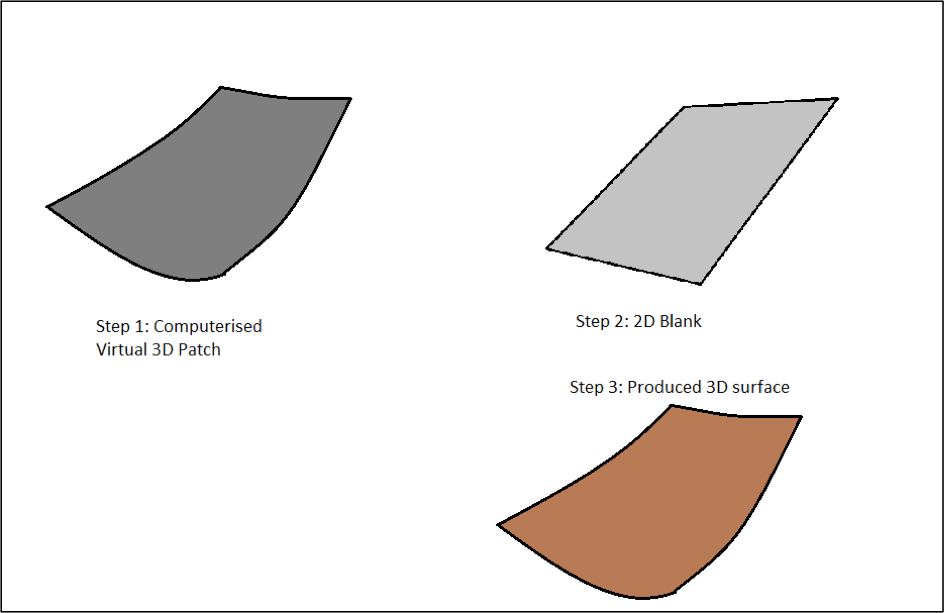
The hull surface is first modelled in a production design software. Welding seams and butts are marked in advance. So, let us assume, for the purpose of understanding this process, that the intended shape to be obtained is a part of the curvature at the bow. The desired shape of the plate in the computerised format is called the virtual 3D patch. Algorithms are so designed that this serves as an input to the CNC machine which cuts out a 2D plate of such shape and size (which is called 2D blank), so that when the 2D blank is hot-worked, it produces the required 3D surface geometry.
- Developable Surface: Any 3D surface that can be obtained directly by rolling or bending a 2D plate is called a developable surface. For example, the bilge strake of a ship usually has an ellipsoidal or circular curvature. This is obtained by directly passing a flat plate under a set of rollers, and the process is repeated until the required curvature is obtained.
A shipyard uses various methods to bend sections, plates, stiffeners into the required 3D geometry. The most widely used methods are discussed below:
Hydraulic Press
Hydraulic presses are used in plate and section formation for a wide range of purposes, like bending of plates, straitening of pre-bent plates, flanging (in case of sections like beam knees), and swaging of plates.
Hydraulic pressing is a cold work, hence there is no residual stress induced on the worked plate. Another advantage of this process is its very low capital cost.
However, there are some disadvantages to this method. Elastic spring-back is a common phenomenon in case of bending by hydraulic press. To understand this, we need to go back to the basics of stress strain curve. When the hydraulic ram hits the steel plate, it induces a stress on the plate, which is more than the proportional limit. As a result, the plate enters the elastic region. When the plate is removed from the hydraulic ram (i.e. it is unloaded), the unloading takes place along a line that is parallel to the stress strain curve up to the proportional limit (See Figure 2).
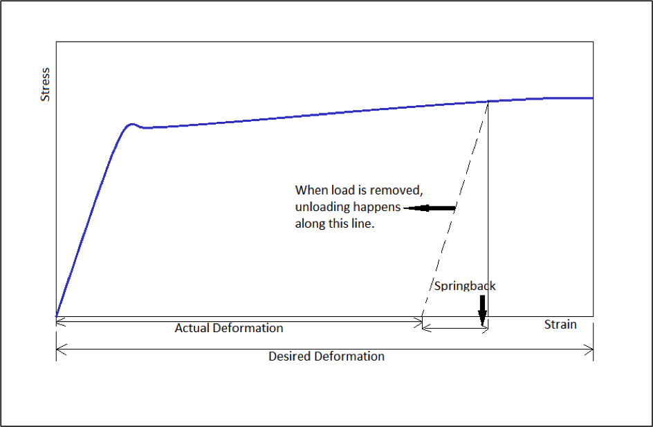
Thus, after load is removed, the actual deformation obtained is less than what was actually required. This is called elastic springback. To prevent this it is important to choose the proper value of stress to be induced onto the plate for a particular deformation.
Other disadvantages of this method are requirement of skilled and experienced labour, and implementation of a proper monitoring system after each ram.
- Plate Rolling:
Shell plates are rolled using this method. A total of three rollers are used in plate rolling. Two lower rollers are driven and the plate is fed above them. One top roller, larger in diameter than the other two rollers, rotates along with the motion of the plate. A hydraulic beam is used above the top roller to apply downward load on the plate (See Figure 3). This method is also often used to correct the curvature obtained by hydraulic press.
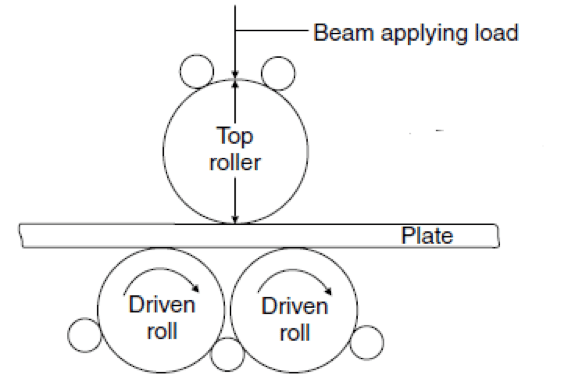
Another type of plate roller is the pyramid full circle roll, which is used to roll a straight plate into a full circle. This is done to obtain sections like masts, derrick posts, bow thruster tunnels.
- Heat Line Bending:
The above two methods were cold working methods of plate and section bending. Heat line bending uses thermal means to induce bending moment, which in turn gives rise to curvatures in plates.
In line heating, the flame torch is applied along a line on the plate. Since the torch is applied only on one surface of the plate, it results in a temperature gradient along the thickness of the plate as shown in Figure 4 (Section AA’).
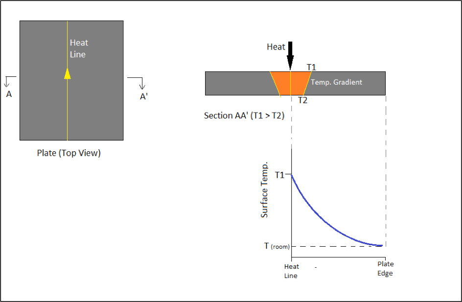
In Figure 4, the graph shows how the surface temperature varies from the heat line to the edge of the plate (which is almost at the room temperature). Therefore, line heating has two main effects:
- Part of the breadth of the plate remains unaffected by the heat. We will see soon, how this helps in achieving the required bending effect.
- A temperature gradient is created along the thickness of the plate.
The parameters to be controlled in line heating are the amount of heat, speed of torch, and rate of heating. The quality of work depends on these parameters, and they are altered depending on the material and thickness of the plate.
We will now see how line heating affects thin and thicker plates differently.
For thin plates, there is no temperature gradient along the thickness of the plate. In simpler terms, after the torch is applied, the temperatures on both the surfaces along the line of heating is same, as shown in Figure 5.
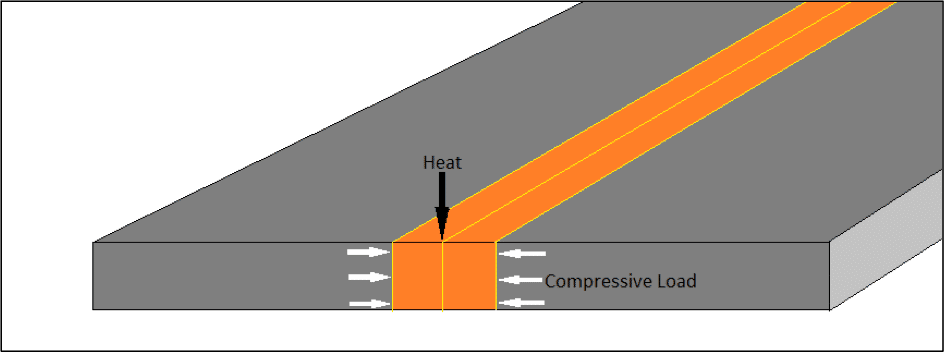
The heated regions of the plate (shown in orange in Figure 5) would try to expand due to increase in temperature. But the remaining part of the plate, being at lower temperature, acts as a clamp, restricting the lateral expansion of the heated area. This gives rise to compressive loads on the heated area as shown above. As a result of this, the heated area contracts laterally, increasing the plate thickness along the heat line (as shown in Figure 6). This leads to shrinking of the entire plate (Figure 6).
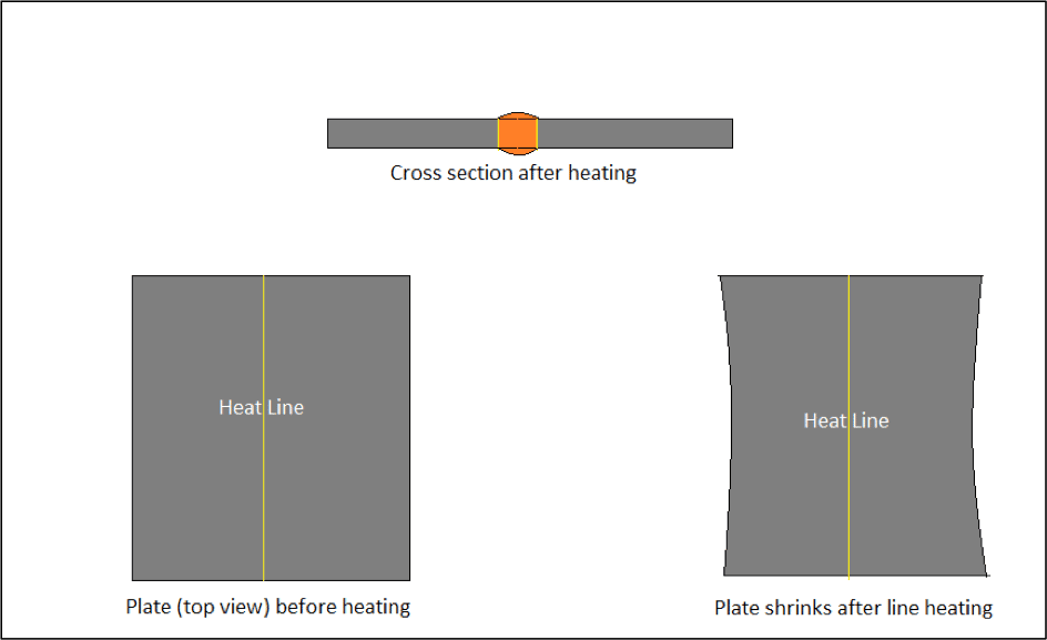
Note here, that in case of thin plates, the purpose of bending the plate (or giving it a 3D curvature) is not achieved. In spite of that, why is line heating used to bend plates? The answer to this is in the following section that deals with line heating on ‘thick’ plates.
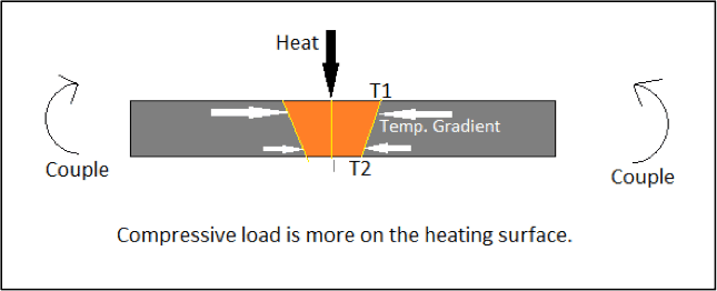
For thick plates, a temperature gradient is achieved along the thickness (as in Figure 7). As explained above, local heating gives rise to compressive loads on the heated area. But in this case, the compressive load at the heated surface will be more than the compressive load on the other surface (due to difference in temperatures on both surfaces). As a result, a couple is generated, as shown in Figure 8. This couple now leads to bending of the plate.
In order to obtain the required 3D curvature, the heat rate is decided by a program and fed to the torch. Gap between the torch and plate surface, diameter of nozzle is also pre-decided by a computer program depending on the curvature. The required curvature is usually not obtained by a single heat line. A pattern of multiple heating lines and their sequence is computed by a program for the required geometry.
Frame Bending
For stiffening of sections at the bow and stern, the frames too need to be bent to the required curvatures. Frames can be bent using both cold work and hot work. The methods are discussed below.
- Inverse Curve Method:
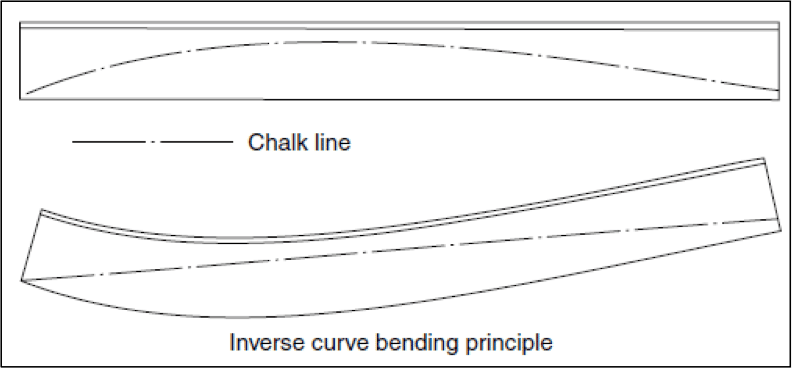
This is a typical cold work method used to achieve required curvatures in frames. The inverse curve of the required curvature is first drawn on the web of the frame. The web is then cold worked and bent to the required curvature, the accuracy of which is checked for until the inverse curve appears as a straight line on the web, as shown in Figure 8.
- Bending by Line Heating:
The most common hot working method used to bend frames is by the principle of line heating. The same principle of bending moment generated due to compressive stresses is used to bend the web of frames, as shown in Figure 9. Here, the heat is applied in a pattern at certain intervals on the web of the frame. The amount of heat or speed of torch at each location determines the final shape of the curve.

The above topics have spanned over the entire plate rolling, bending, and frame bending processes which are carried out in the Hull shop of the shipyard. The flow of material and carrying out of all the processes we have understood above and in the previous article, are now shown schematically in the following figure in order to give you a clear idea of the flow of material in a shipyard.

In reference to Figure 10, we have seen all the processes involved till cutting, marking, shaping and bending. What was not explained, was the process that runs parallel to all the above – preparation of outfit materials, pipe bending and outfit fabrication. We will first look into this, and then see how they are assembled together.
Preparation of Outfit
As soon as the material for the ship is ordered, most of the orders for a large percentage of outfit items are also placed by the shipyard, so as to keep the hull fabrication and outfit installation processes in parallel. This reduces the building time, but also requires advanced design processes and proper building management plans. This is called advanced outfitting (which is explained in detail here [please hyperlink the articles on Advanced Outfitting]).
Since the details of outfit preparation are not in the scope of this article, we will shift focus to the sequence of processes. In parallel to plate stocking, plate surface preparation, cutting and bending, outfit equipment like pumps, compressors, heat exchangers, etc. and their corresponding piping systems are ordered. The pipes are bent in the pipe bending shop, and the outfit items are kept ready to be installed onto the hull assemblies.
Assembly of Hull Units
Once the plates and frames are prepared and given the required shape, they are welded according to the structural drawings prepared by the design department of the shipyard. The hull is divided longitudinally into blocks (Figure 11), and each block is again divided into assemblies and sub-assemblies.

After plates and sections are machined, they are ready to be welded into two dimensional structures called sub-assemblies. This is carried out in the Prefabrication Shops. A sub assembly would consist of a plate (Straight of curved), and its corresponding strengthening stiffeners welded to it. For example, for a particular block, a panel of outer bottom shell and outer bottom longitudinals would form a sub assembly. Assemblies may be prepared by manual welding or automatic welding, depending on the complexity of the job and the efficiency of the shipyard. Often, flat panels are manufactured by automatic welding, where the stiffeners are marked on the panel, and welded by robotically controlled welding torches.
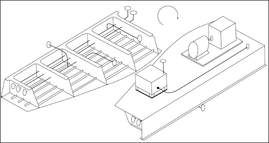
Adjacent sub-assemblies are welded together to form three dimensional structures called block assemblies. The size of assemblies are decided in the designing stages, considering the carnage capacities and special layout of the shipyard. It is ensured by all shipyards that all joining processes are carried out mostly by downhand welding. In case of blocks towards the aft of the ship where equipment and pipework are a major part of the blocks, first the assembly is upturned to fir the piping on the underside, and overturned again by cranes for fitting of the equipment. For example, the double bottom is used to house pipes, and most of the equipment are housed on foundations over the double bottom plating. In order to manufacture such an assembly with a pipe and associated pipework, first the assembly is turned so that the pipework can be installed on the underside of the double bottom. The assembly is them overturned by cranes for the pump to be erected on the double bottom plating. A schematic of this process is shown in Figure 12.
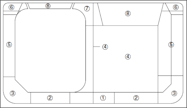
Adjacent assemblies are welded to erect a block. For example, for a particular block of a double hull tanker as shown in Figure 13, the units or assemblies that the block consist of are as follows:
- Double bottom centre unit.
- Double bottom wing unit.
- Bilge unit.
- Longitudinal or transverse bulkhead unit.
- Double hull side unit.
- Deck side unit.
- Centre deck unit.
- Main deck unit.
The assemblies are erected and welded to their adjacent structures in the above sequence. The sequence is pre-decided in the design and modelling stage using CAD/CAM optimisation techniques, so that minimum shifting of assemblies are required, and proper use of carnage facilities is ensured.
Once all blocks are erected based on their welding sequences, they are now ready to be joined. This process is carried out at a different site. It is that process we will discuss in the next article of this series and see how a ship is prepared to be delivered to the client.
Do you have info to share with us ? Suggest a correction
Latest Naval Arch Articles You Would Like:
Subscribe To Our Newsletters
By subscribing, you agree to our Privacy Policy and may receive occasional deal communications; you can unsubscribe anytime.
Web Stories










Thanks for sharing all the diagrams depicting the process of building a ship. It is fascinating to learn how all the parts come together. I found the sections about preparation and assembly particularly interesting. It’s fun to think about the pipes and other accessories being formed in parallel to the process of manufacturing the ship parts. Are the pipes formed using heat, like some parts of the ship? https://www.inductabend.com.au/special-services